
Camstat Fan Limit Control Wiring Diagram
All wiring must conform to local electrical ordinances. I have bought the correct replacement part (camstat f561 7 universal replacement combination fan and limit control).
Blower randomly doesn't start Community Forums
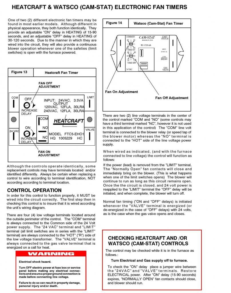
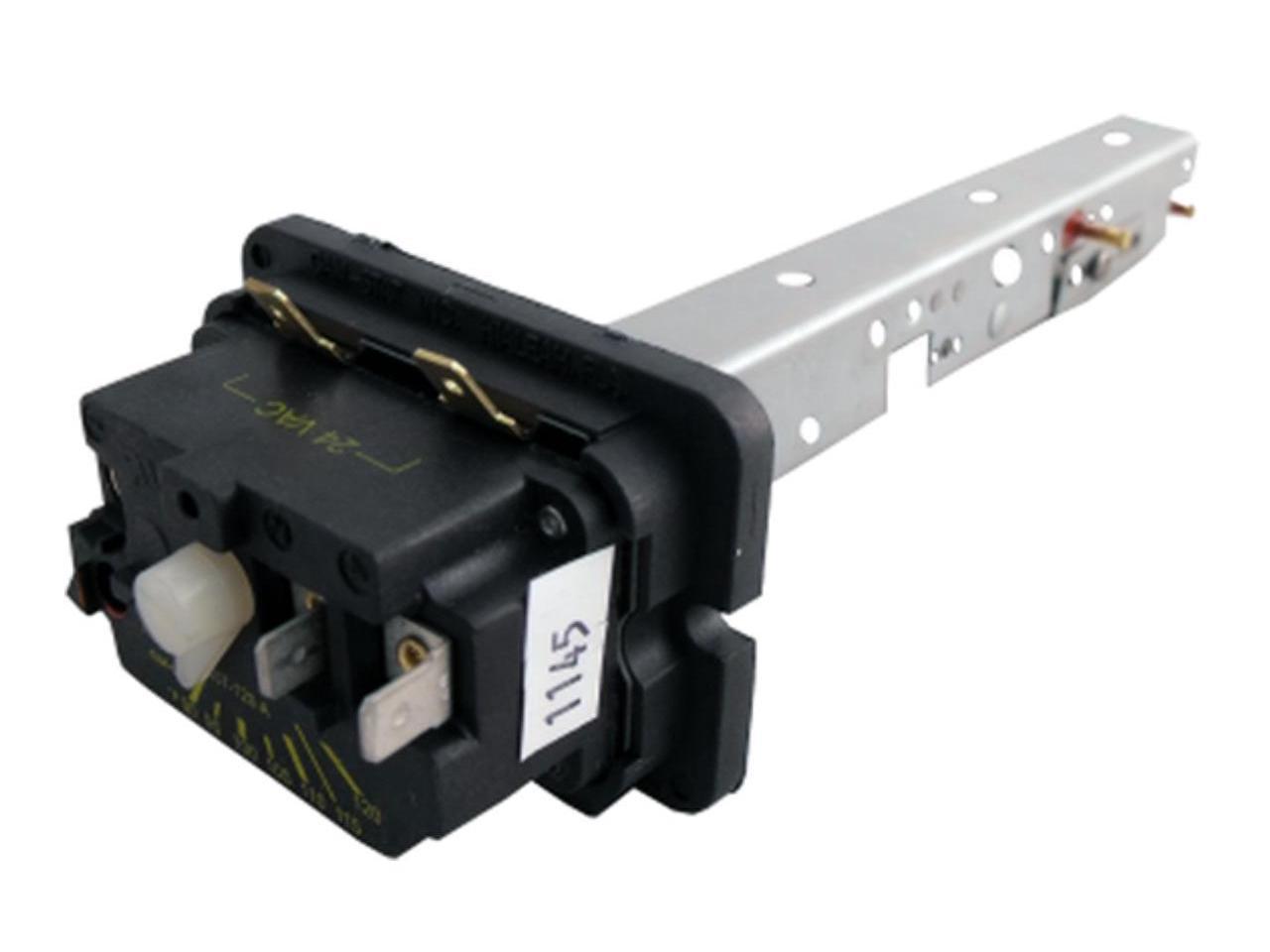
When the camstat heater reaches the correct temperature, the wire terminals send a signal to start the fan operation.
Camstat fan limit control wiring diagram. R sealed units parts co., inc po box 21, landmark place allenwood, nj 08720 usa w.sup. Furnace er motor wiring question need help connecting wires from new fan limit improvement ridgid control troubleshooting diagnosing the duotherm pilot model building diy door 3 sd problem home diagram older heater. 1000w over any distance demands cabling that is a centimeter thick.
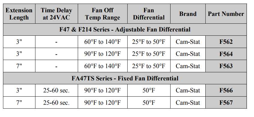
Wiring diagram april 30, 2020 06:32. 25 to so limit t. Time start fan control for heat assist.
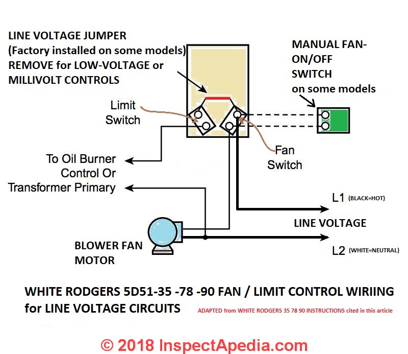
The following example of wiring a fan limit control switch is based on advice from the honeywell tradeline l4064b. The following is a wiring diagram for a honeywell fan limit switch control. Camstat blower control part number bc7070 time delay adjustable on and off 0 to 4 minutes instructions included.
2 and 4 are for the fan switch on the camstat. How to install & wire the fan & limit controls on furnaces. As the illustration shows, the two limit terminals are on the upper and lower right side of the l4064b control.
Supco camstat fan & limit control, 7. How to find voltage ampere rating of switch plug outlet receptacle. Limit temperature adjustment 150 to 250f.
L59 series limit controls • spdt switch • user adjustable temperature setting fan part a1 part length temp off fixed no. 32+ camstat fan limit control wiring diagram pictures. It shows the components of the circuit as simplified shapes, and the talent and signal connections.
Falts combination fan/limit control r inc. If you had the wiring diagram from the unit it would help, the control is a fan/limit a fan control and high limit it is possible that 2 wires are for the fan and 2 are for the limit, your problem is which 2, the honeywell control is clearly marked what side is what and when working with hi and low volts the jumper must be broken, you got that far, if you had nade note of where they were. The honeywell fan side which is left on the diagram i provided you will use 2 and 4 wires of the cam stat and the limit which is right side of the honeywell will be used for the 5 and 6 terminals on the that were on the camstat.
Installing a new cam stat in furnace. Ships from and sold by ohio supply. I have a carrier (originally day & night company) model no.
Replacement for icp (arcoair, comfortmaker, heil and tempstar) numbers hq1005229cs, f7070, 1005229, 1065750. 150 °f to 250 °f. Supco offers the complete line of camstat controls.
Includes a heat assist time start time delay turns on the blower as a function of time and/or temperature after the room thermostat calls for heat. Time delay turns on blower as function of time and/or temperature after call for heat. Turn the power off at the furnace and go a step further for safety and turn the power off at.
Camstat fan limit control wiring diagram moreover furnace limit switch wiring falts57c05ta falts fan & limit controlamazon com camstat falts57c 05t a 7\. For replacing the exact oem heating control components, supco® offers the complete line of camstat® controls. Combination fan and limit control.
Hover over picture to zoom. Before beginning any wiring make sure you turn the power off. Terminals 5 and 6 on the camstat as shown on the wiring diagram i provided you are for the low voltage/limit wires.
The furnace fan is wired between the second set of wire terminals on the camstat. Turns off blower as a function of temperature at dial setting for fan. Limit fa47ts series fan controls witime start fan control (replaces all fa47ts series controls) these are special fan controls with a built in 'heat assist' time delay.
Element length 3 fan off temperature adjustment 90 to 120f. As the air in the furnace plenum warms up the bimetallic spring expands turning a gear which turns the fan limit control dial shown in the photo above. 90 °f to 120 °f.
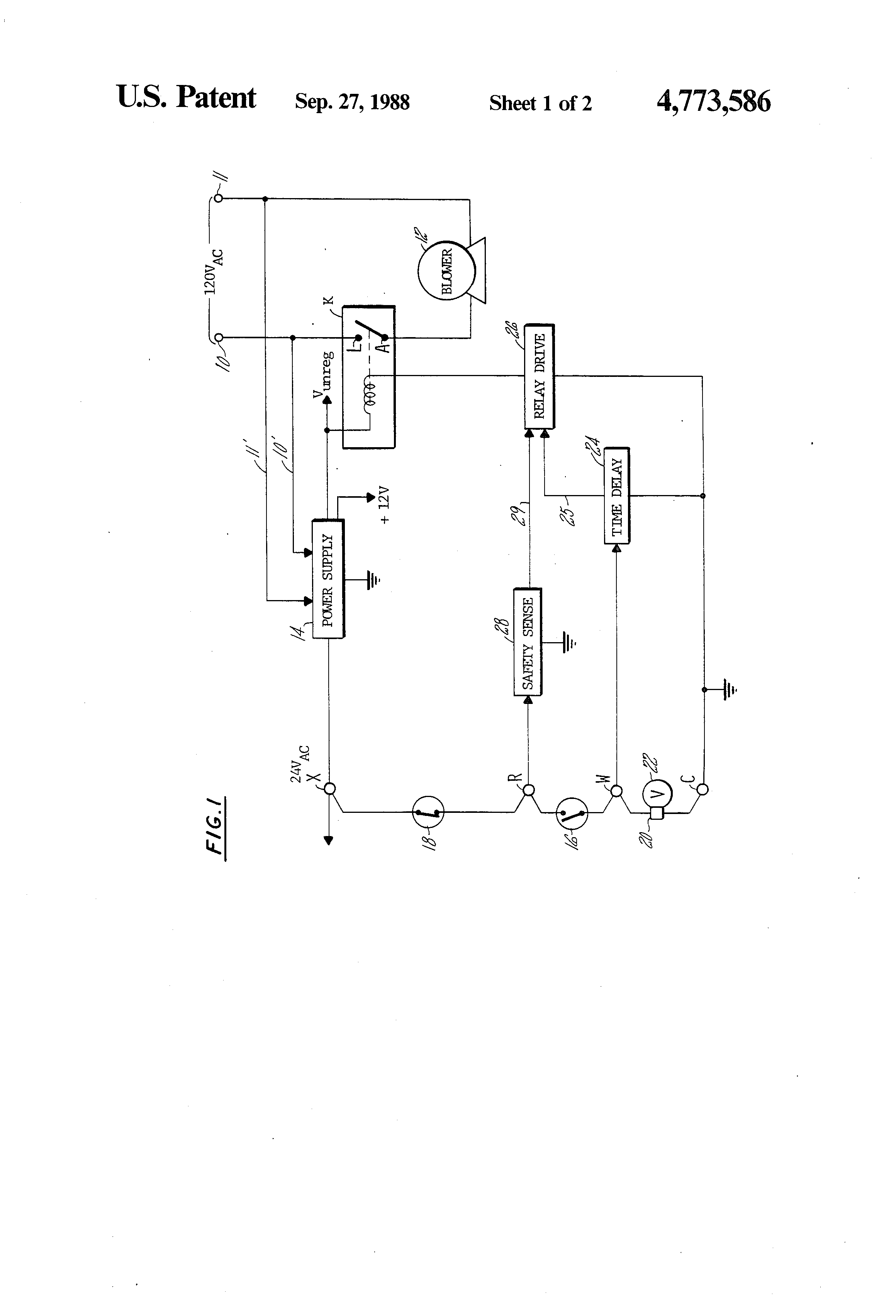
A typical connection is shown in the wiring diagram. Hongso magnetic thermostat switch for fireplace stove fan/fireplace blower kit. Camstat fan limit control wiring diagram wiring diagram is a simplified usual pictorial representation of an electrical circuit.
Camstat fan limit control wiring diagram basic hvac blower wiring wiring library. Time start fan control for.

Camstat fan and limit control FALTS57C05T 120A

CAMSTAT FAN & LIMIT CONTROL FAL3C05TD120A
Blower Limit Switch Wiring Diagram

Coleman 2burner furnace 30 years old how to adjust the fan switch?
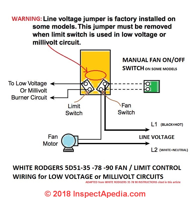
How to Install & Wire the Fan & Limit Controls on Furnaces Honeywell L4064B & All White Rodgers
19 Fresh Camstat Wiring Diagram

Camstat FALTS57C05T120A 7" Fan & Limit Control With Time Delay
Camstat Wiring Diagram

Camstat time start fan control. Part no. FA47TS3110

Wiring Diagram Wood Furnace Wiring Diagram Schemas
Camstat Wiring Diagram
How to Install & Wire the Fan & Limit Controls on Furnaces Honeywell L4064B & All White Rodgers
Camstat Wiring Diagram
Falts57c05t120a Wiring Diagram
Wiring Diagram Wood Furnace Wiring Diagram Schemas

Wiring Diagram Wood Furnace Wiring Diagram Schemas

Falts57c05t120a Wiring Diagram
Help with Carrier fan limit switch, c.1975, please? Community Forums


Falts57c05t120a Wiring Diagram
